 |
|
|
|
|
|
Welcome to the Website for N5814L The Online Refurbishment Record of 1972 Grumman AA-5 Traveler N5914L Serial Number AA5-0014 |
|
|
|
Galleries |
|
Links |
|
|
|
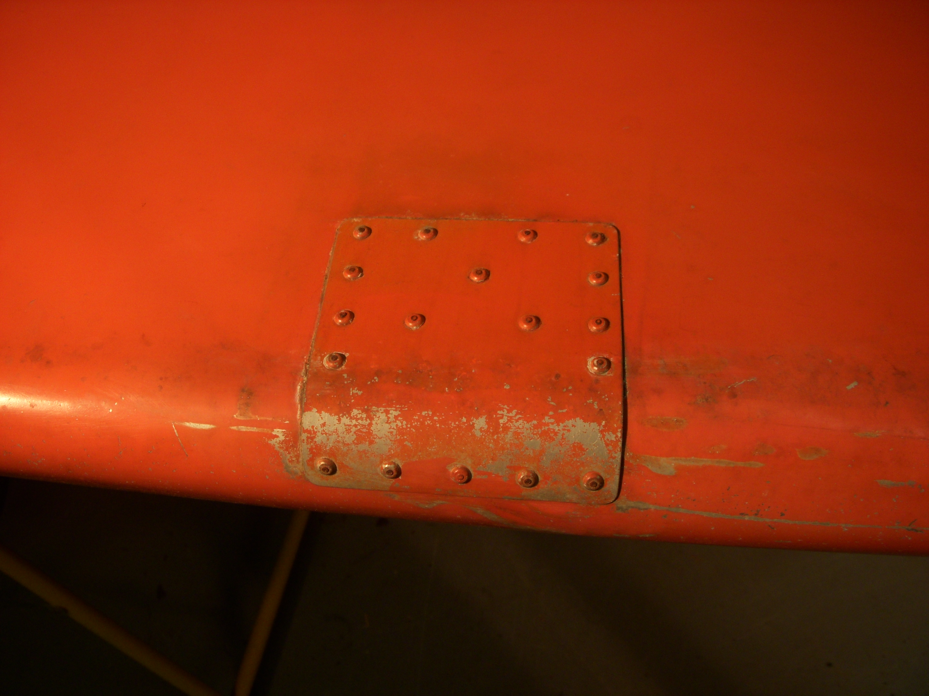
It all could have been so simple... |
 |
|
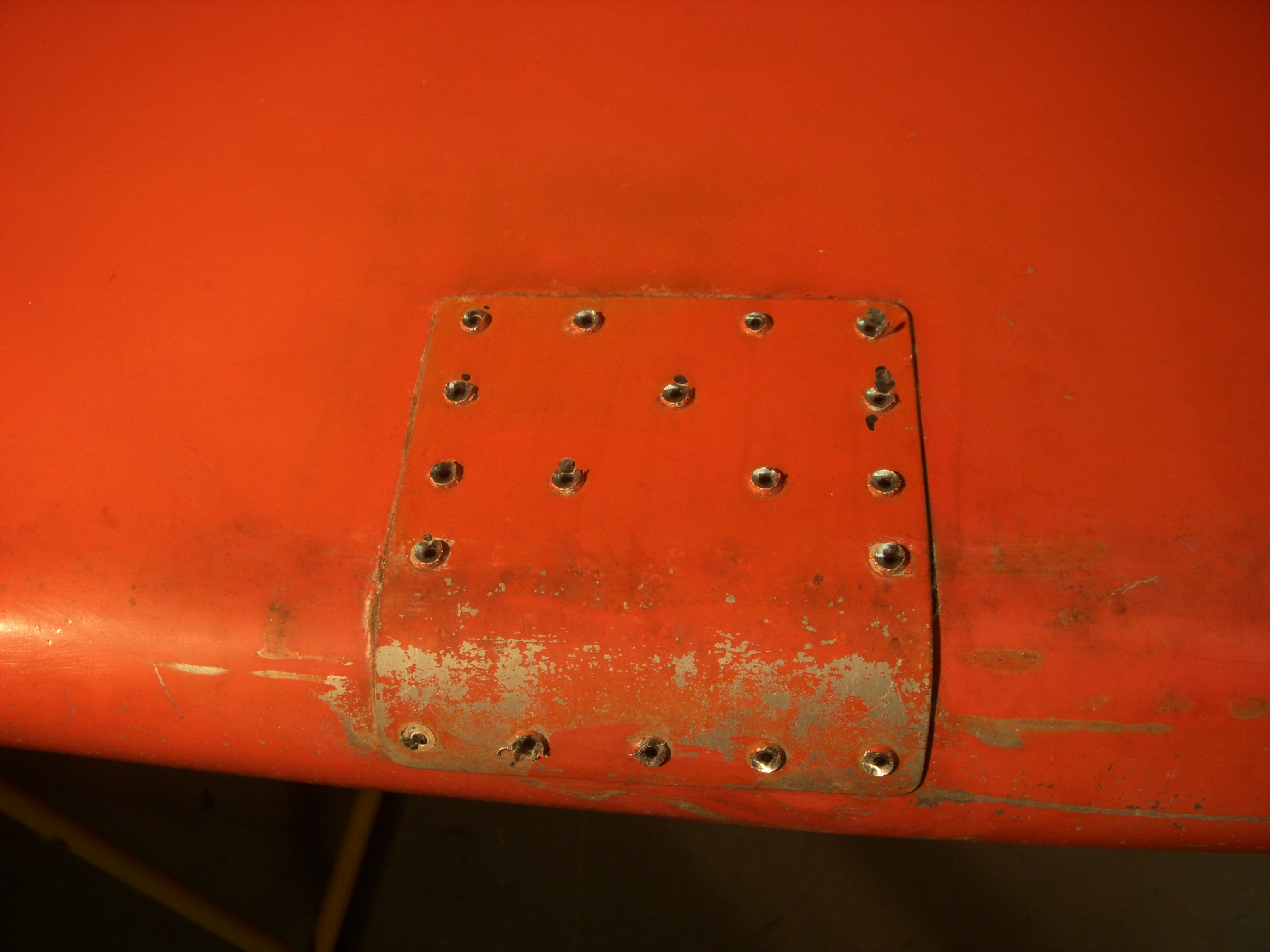
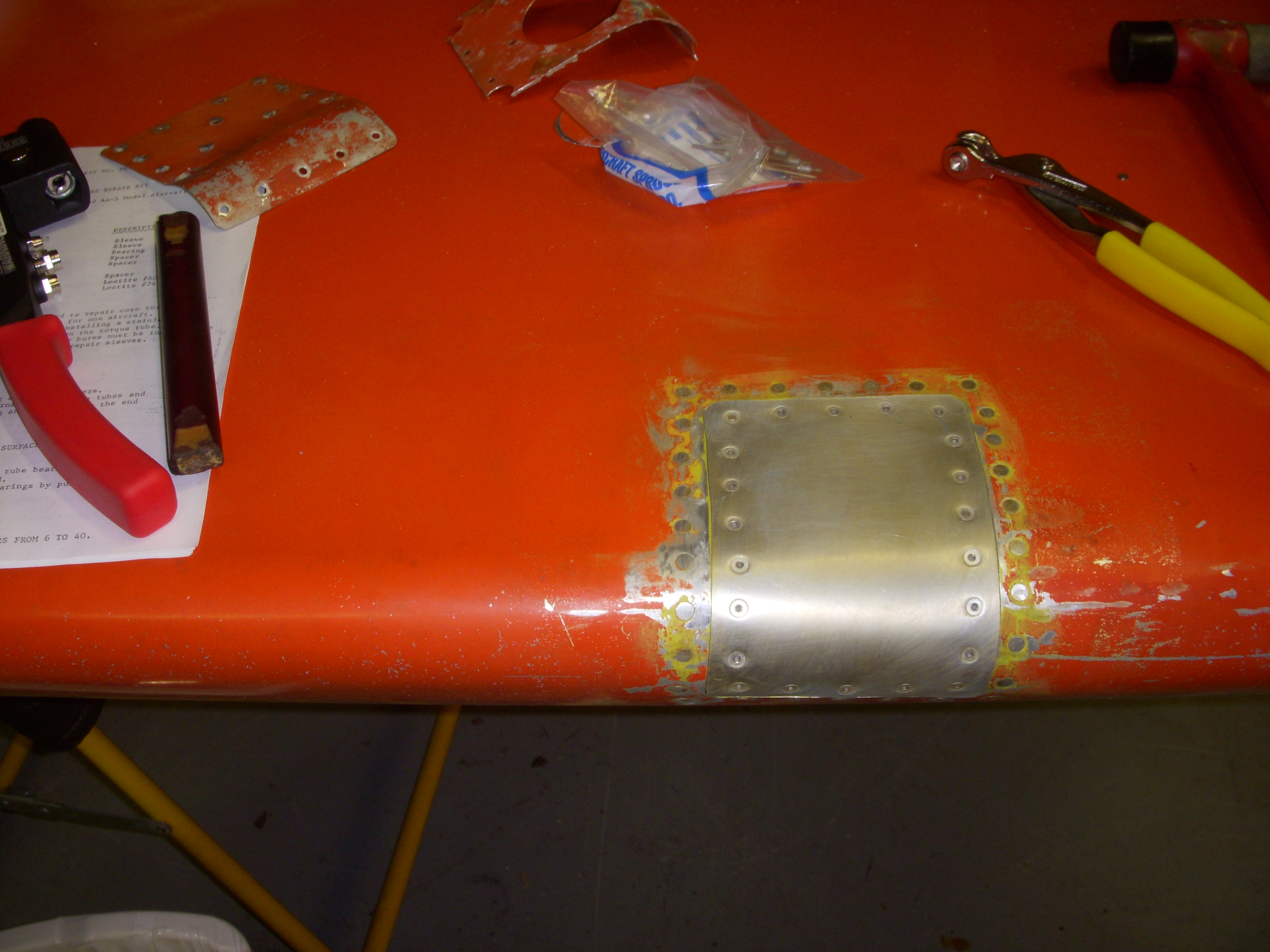
With no idea of what I would find when I pulled the "scab," I began grinding out the the universal-head Cherry Max rivets using my favorite round rotary file chucked up in a mini-diegrider. |
 |
|
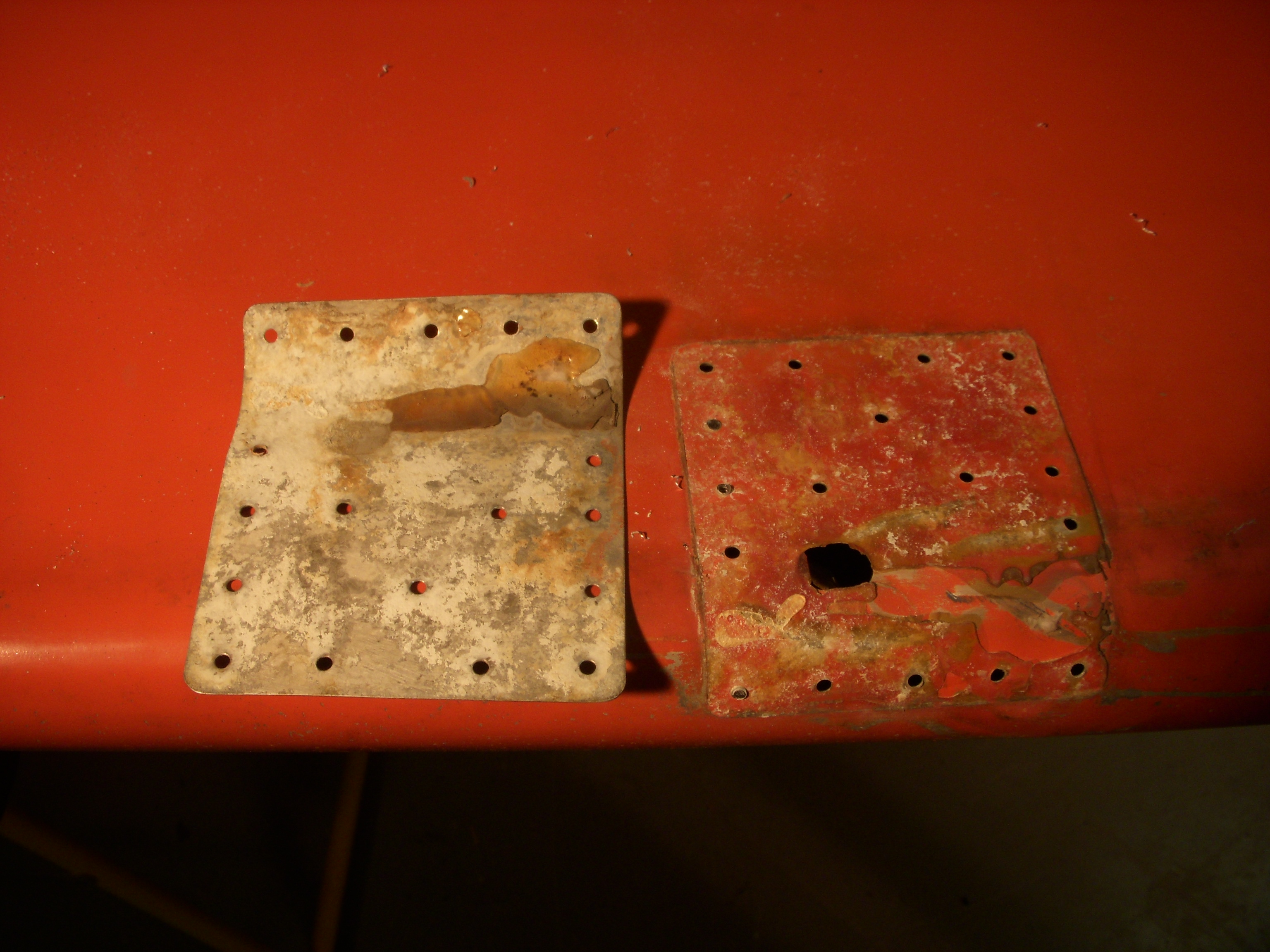
What a mess! The repair appeared to be backed with some sort of epoxy; bare aluminum on the original still-painter substrate. The rivet layout neither conforms to AC 43-13 1B nor chapter 20 of the AA-5 maintenance manual. Aw heck, none of this really conforms to anything. Time to get over that and be glad that the filiform corrosion wasn't more pervasive than that which would be cut away in the process of resolving this "repair." |
 |
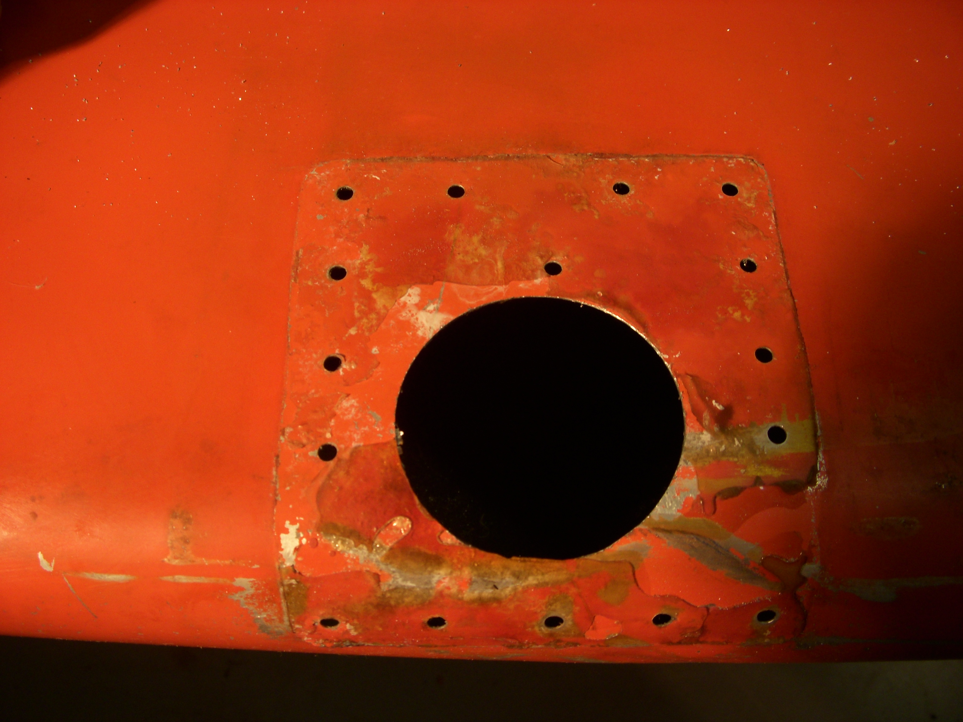
| First step of clearing away the original damage and opening up the skin so that I can get better tool access. |
 |
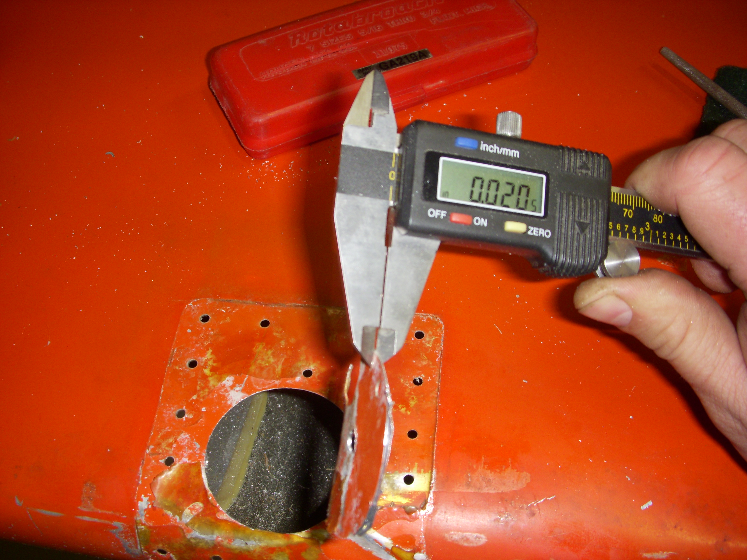
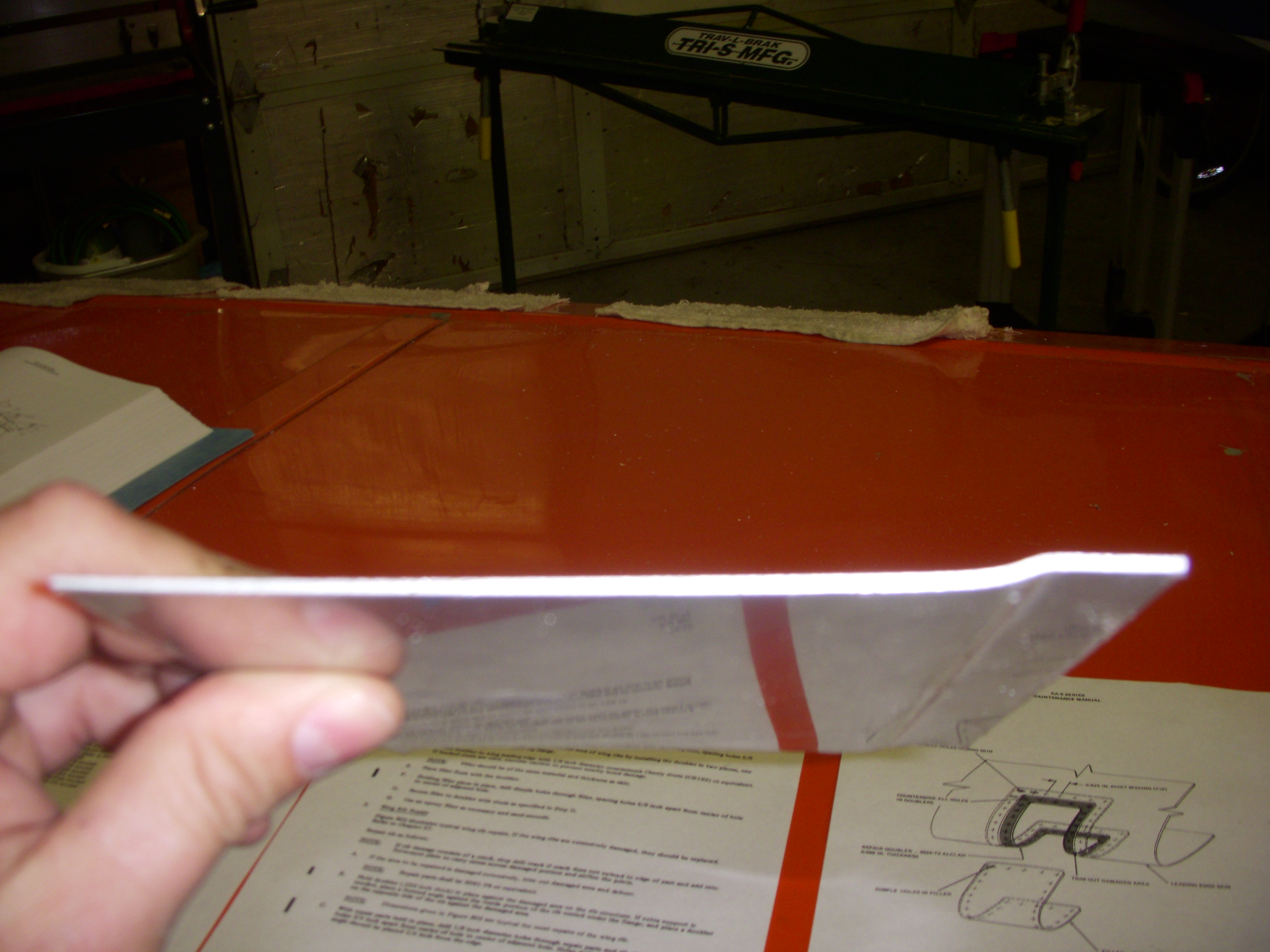
| Not a surprise, the skin material thickness is exactly what the manual said it was supposed to be. Always nice to verify, though. |
 |
|
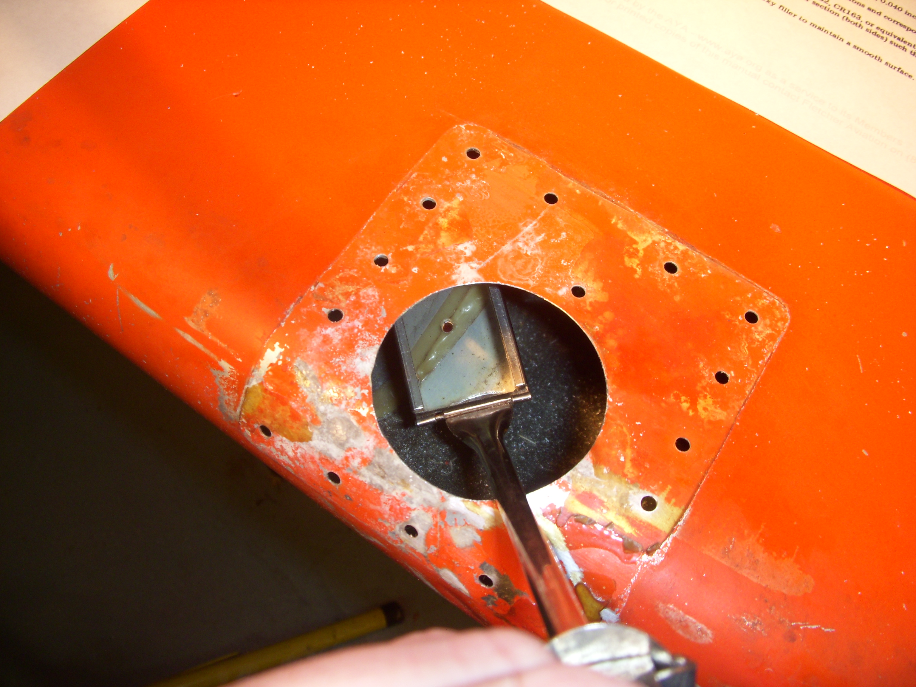
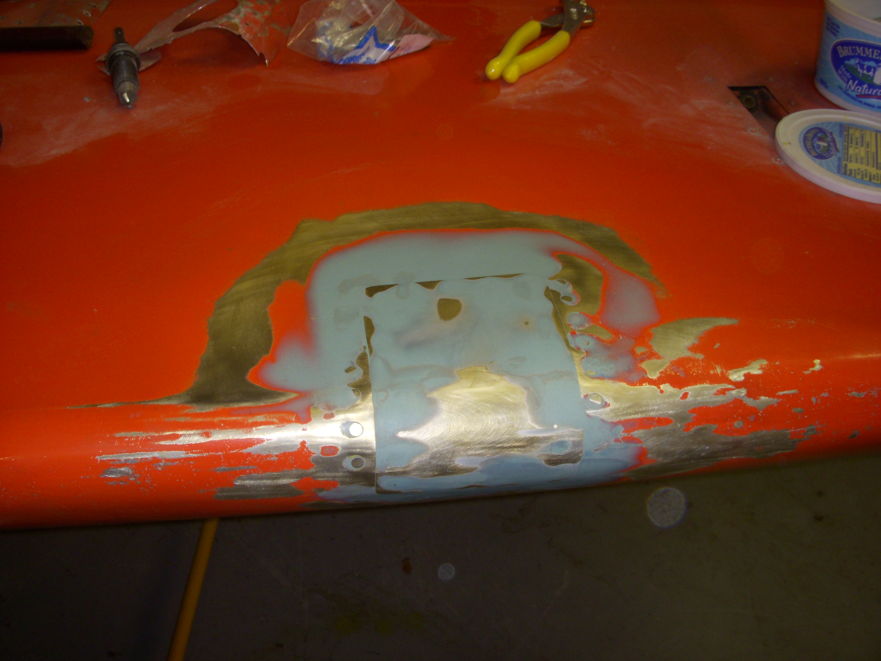
It all could have been so simple... The original damage was actually in a pretty easy to repair location. After clearing away the damaged skin there would have been ample space to install the flat doubler and a flush patch. The whole thing could have been fastened up with blind rivets and done in a snap. Instead, the outboard row of rivets (reflected in the inspection mirror) nicked the adjacent win rib flange... ugh! Now I'll have to create a .040in doubler that both conforms to the contour of the leading edge and incorporates a .025in joggle so that it can step up onto the rib flange and then extend over the rib flange far enough to provide nominal rivet edge distance on the rib flange itself. In short, the original repair caused more problems than it solved in every way. |
 |
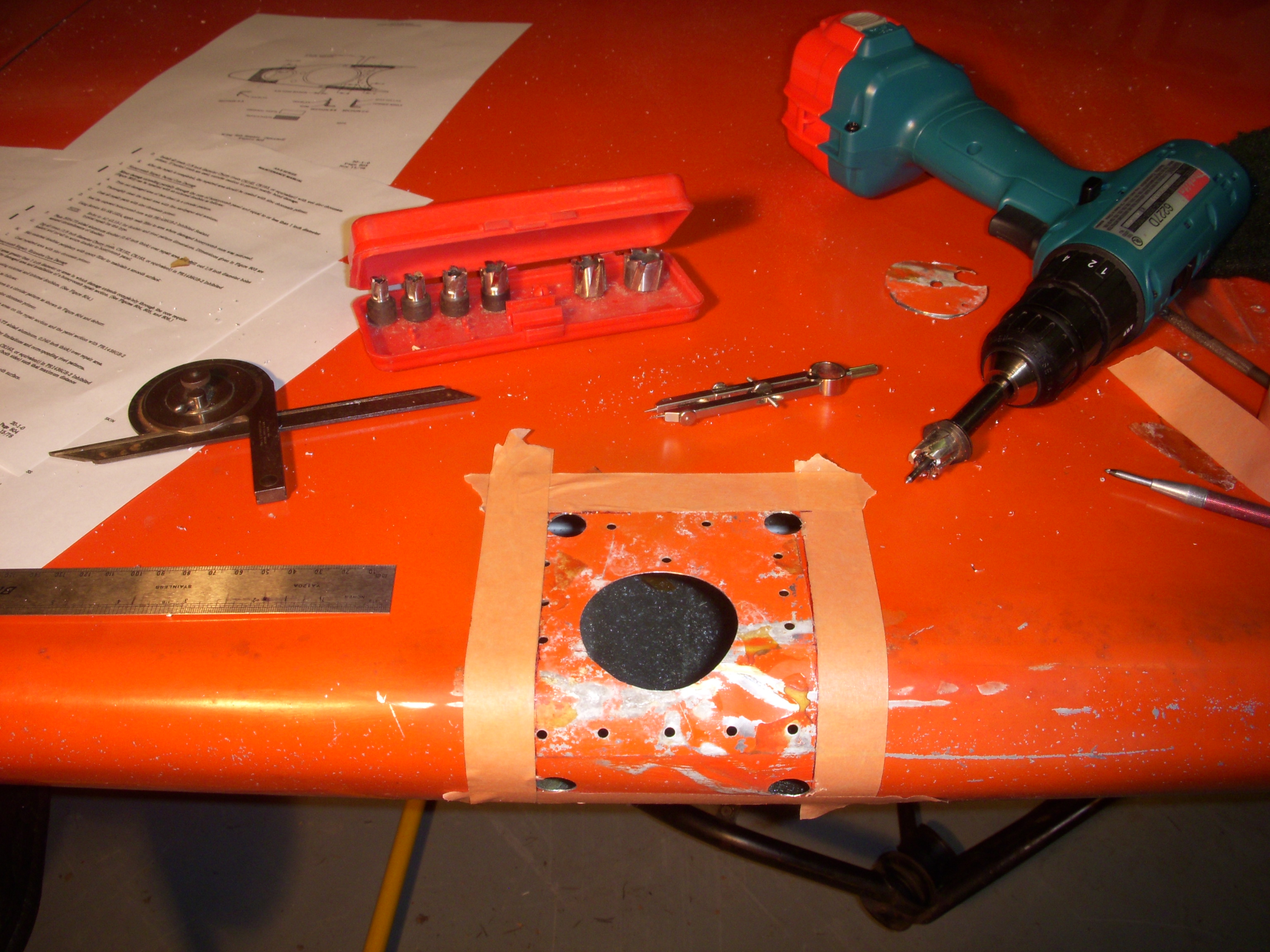
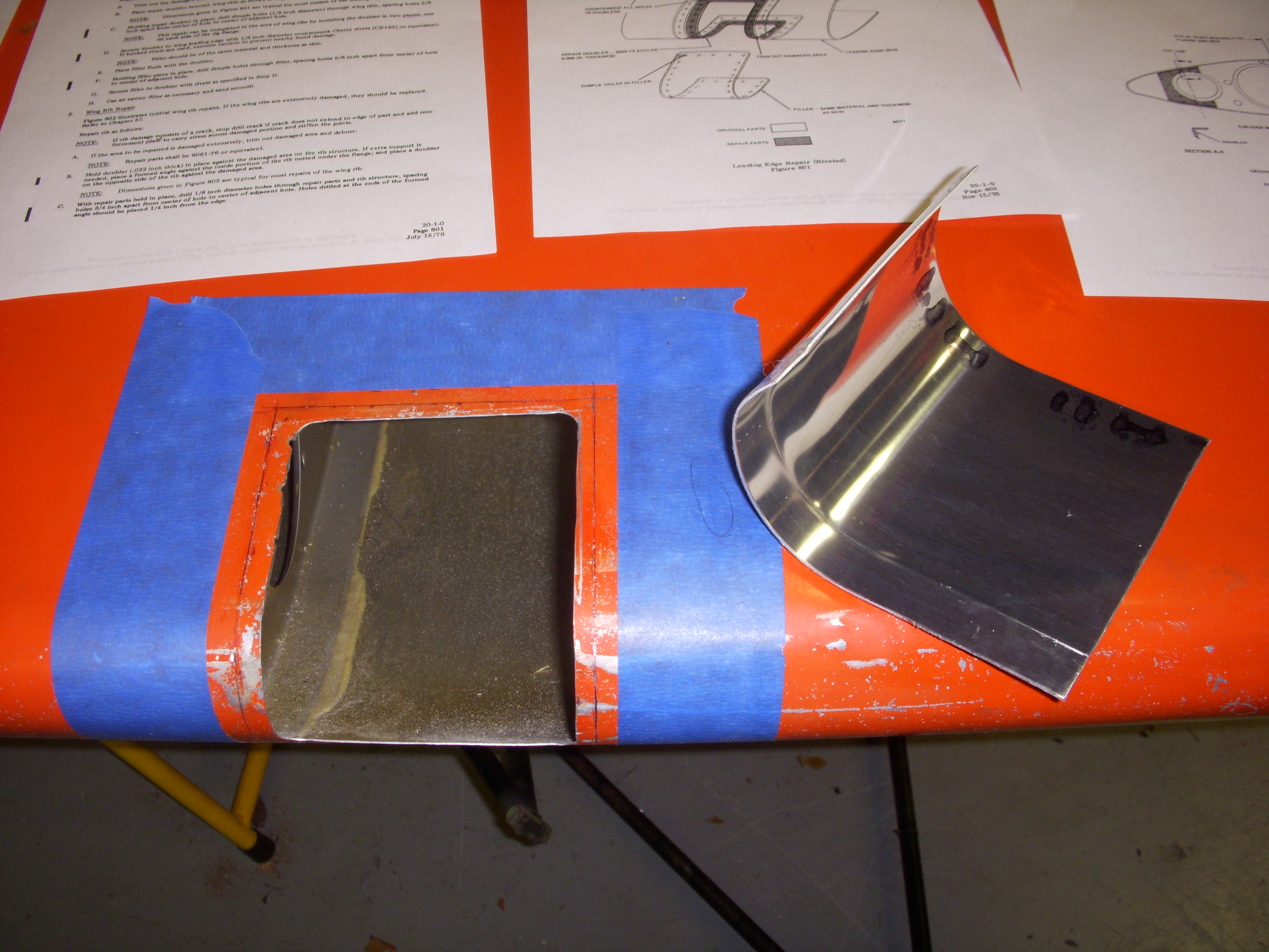
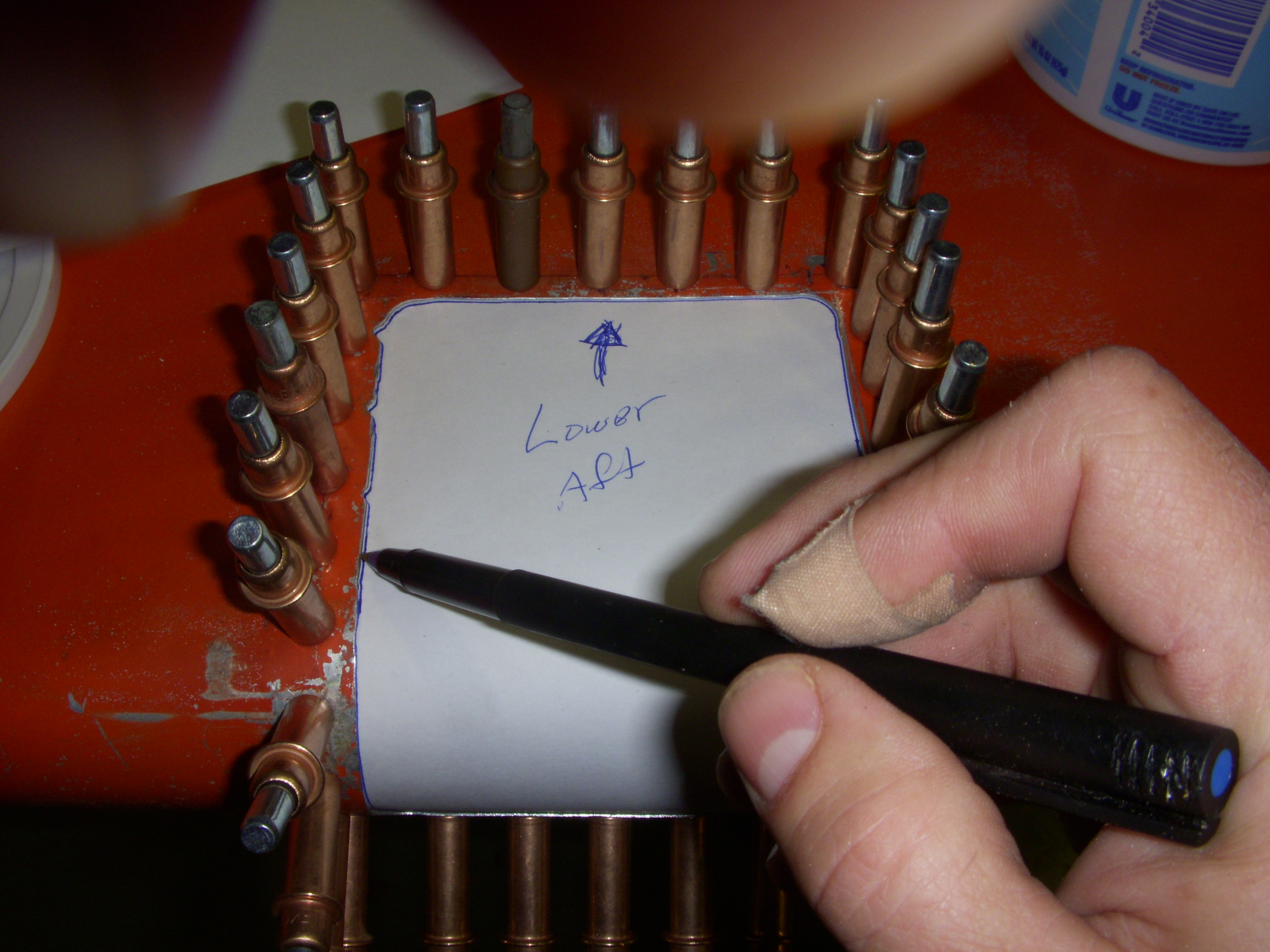
| After locating the wing rib flange with a depth gauge, the line was transferred to the outside in masking tape and the dimensions of the patch were built off of that line. The corners were cut with a Rotobroach cutter. and then straight runs were made with a fiber cutoff wheel on a Dremel tool. |
 |
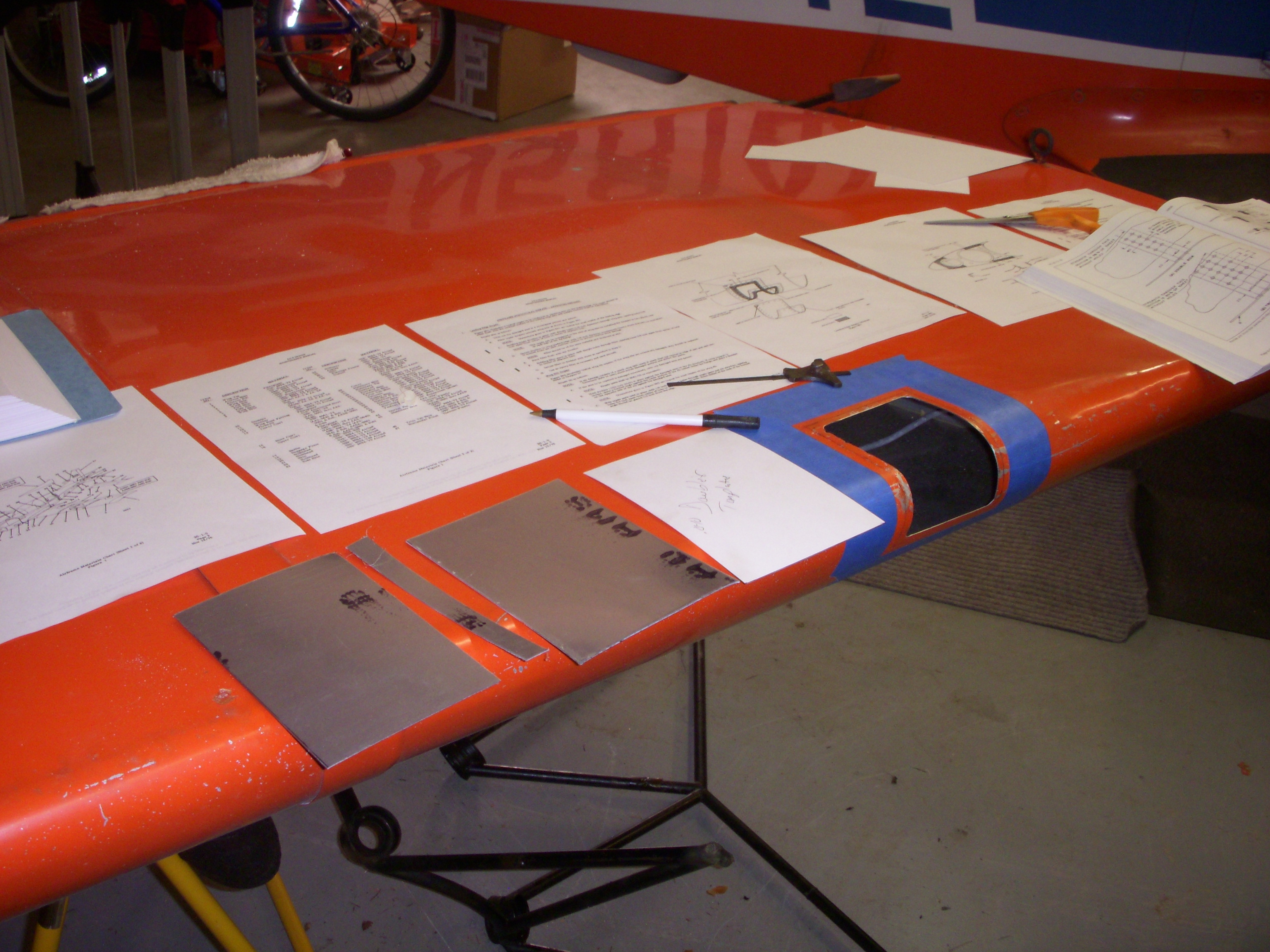
| A template was made to transfer the doubler dimension into a flat plane and the doubler plank was sheared from .040in 2024-T3 Alclad. |
 |
| Stage two, the doubler blank after the getting the joggle treatment. |
 |
| Off to the slip roll. The joggle was "flanked" with .250in shims to both preserve and "true-up" the .250in joggle as the leading edge contour was formed into doubler. |
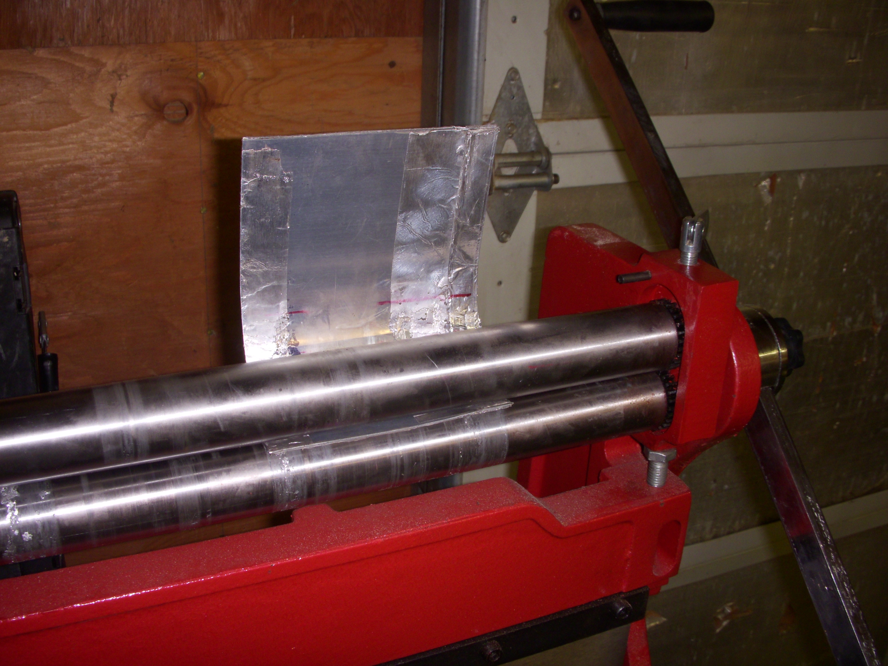 |
| Joggled and rolled to shape, here's the doubler ready to get its center cutout. |
 |
| Fitting up the doubler with spring clamps. |
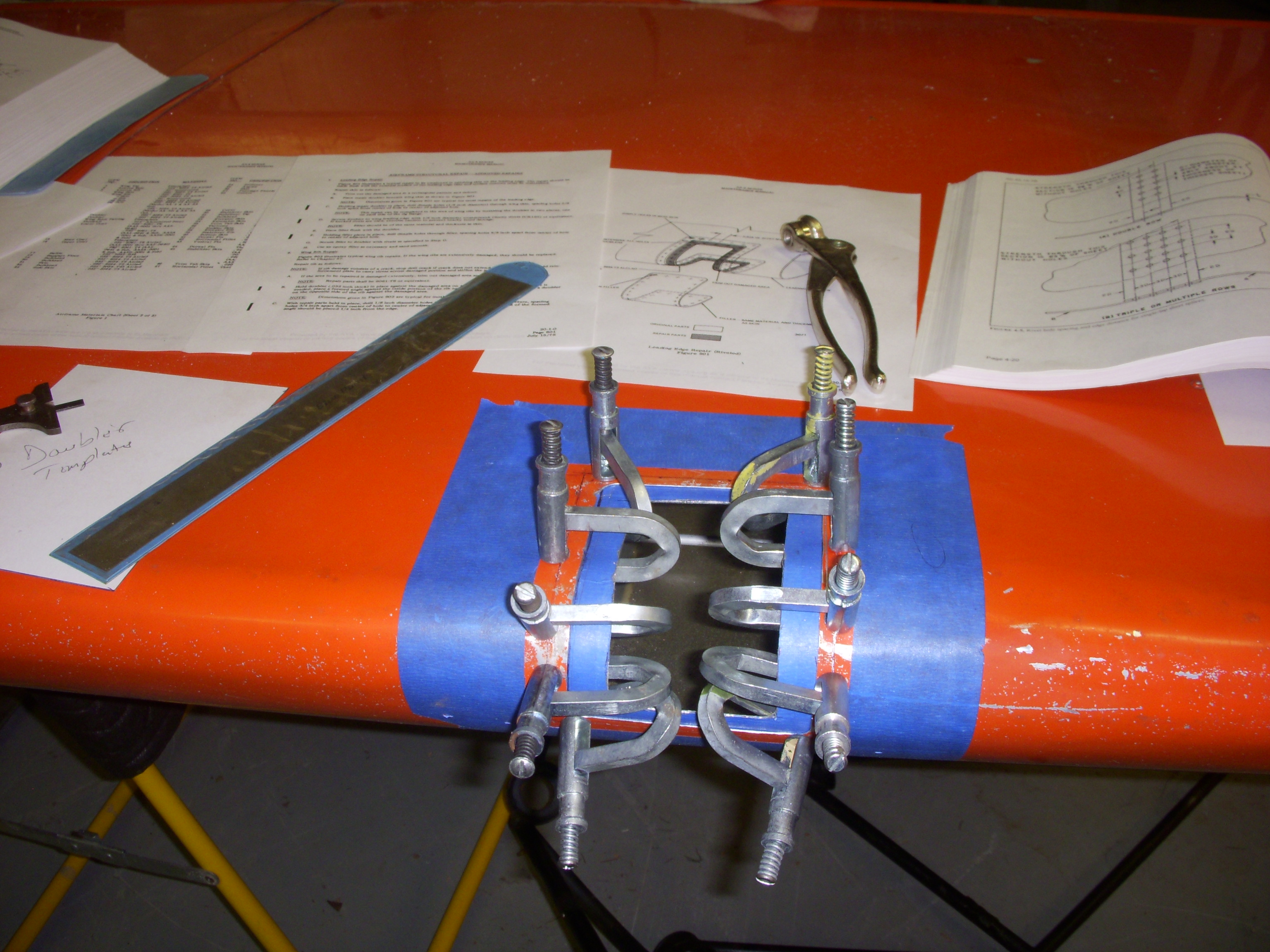 |
| With the doubler in Clecos, it was a simple matter to trace out the flush patch template in cardstock. |
 |
| Doubler drilled and countersunk and flush patch drilled and dimpled. Then, both parts took a bath in etch and Alodine. |
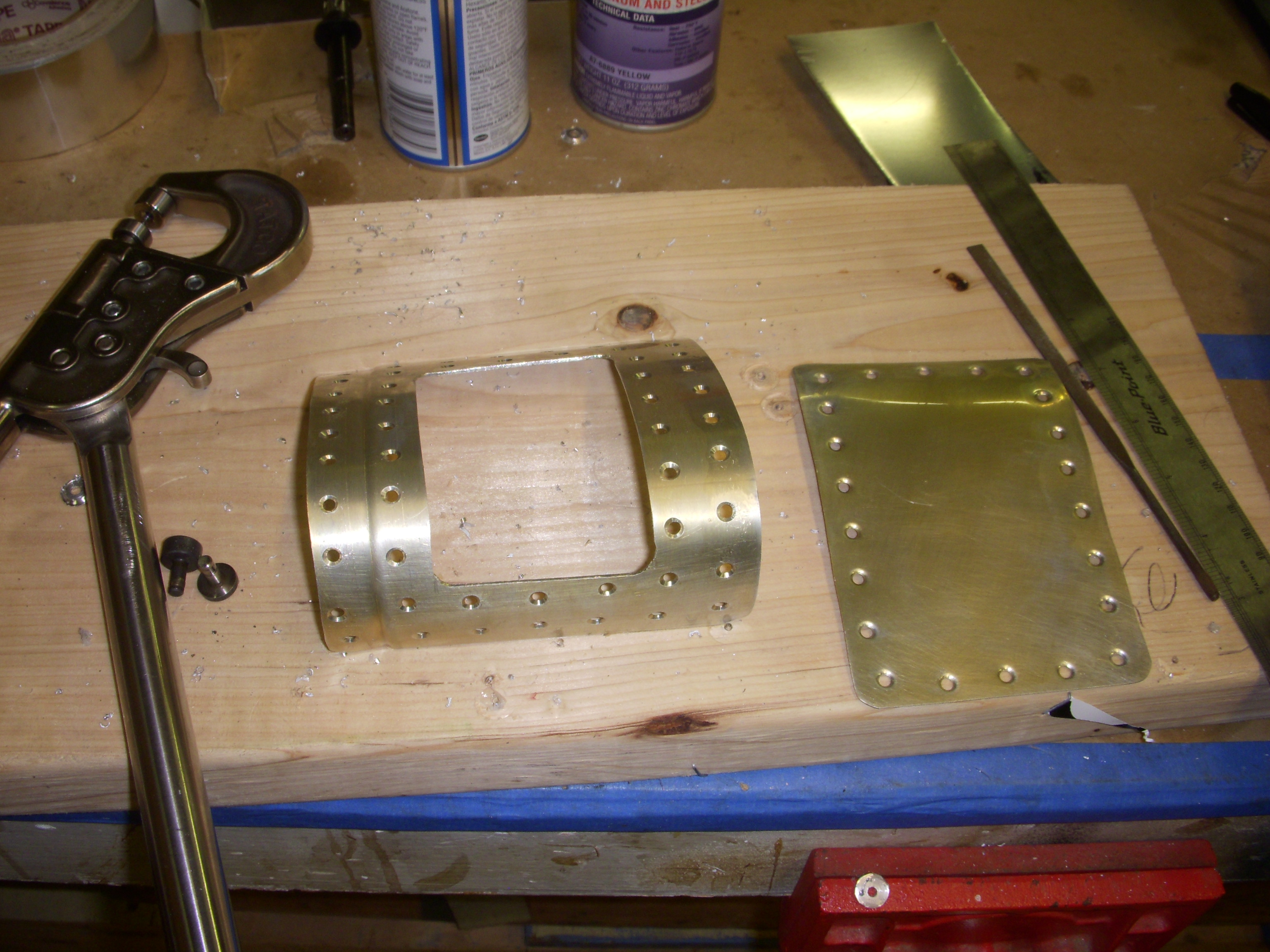 |
| Doubler chromated and permanently installed with hand-squeezed AN426-4 AD rivets. |
 |
| Flush patch in Clecos, getting its final fit just before riveting. |
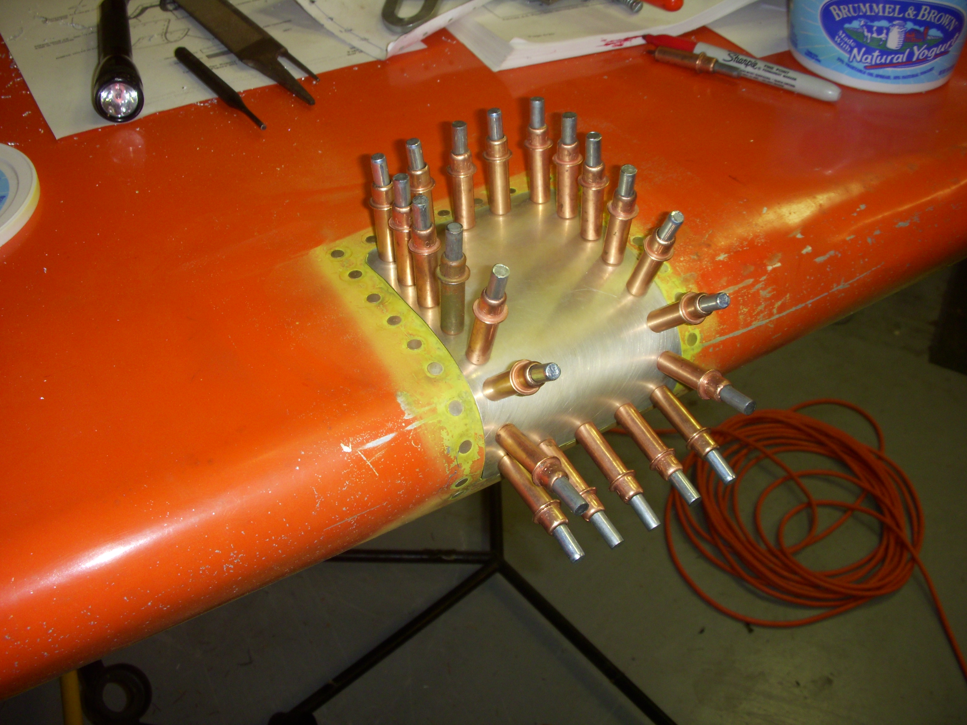 |
| Flush patch permanently installed using self-plugging Cherry Max countersunk rivets. |
 |
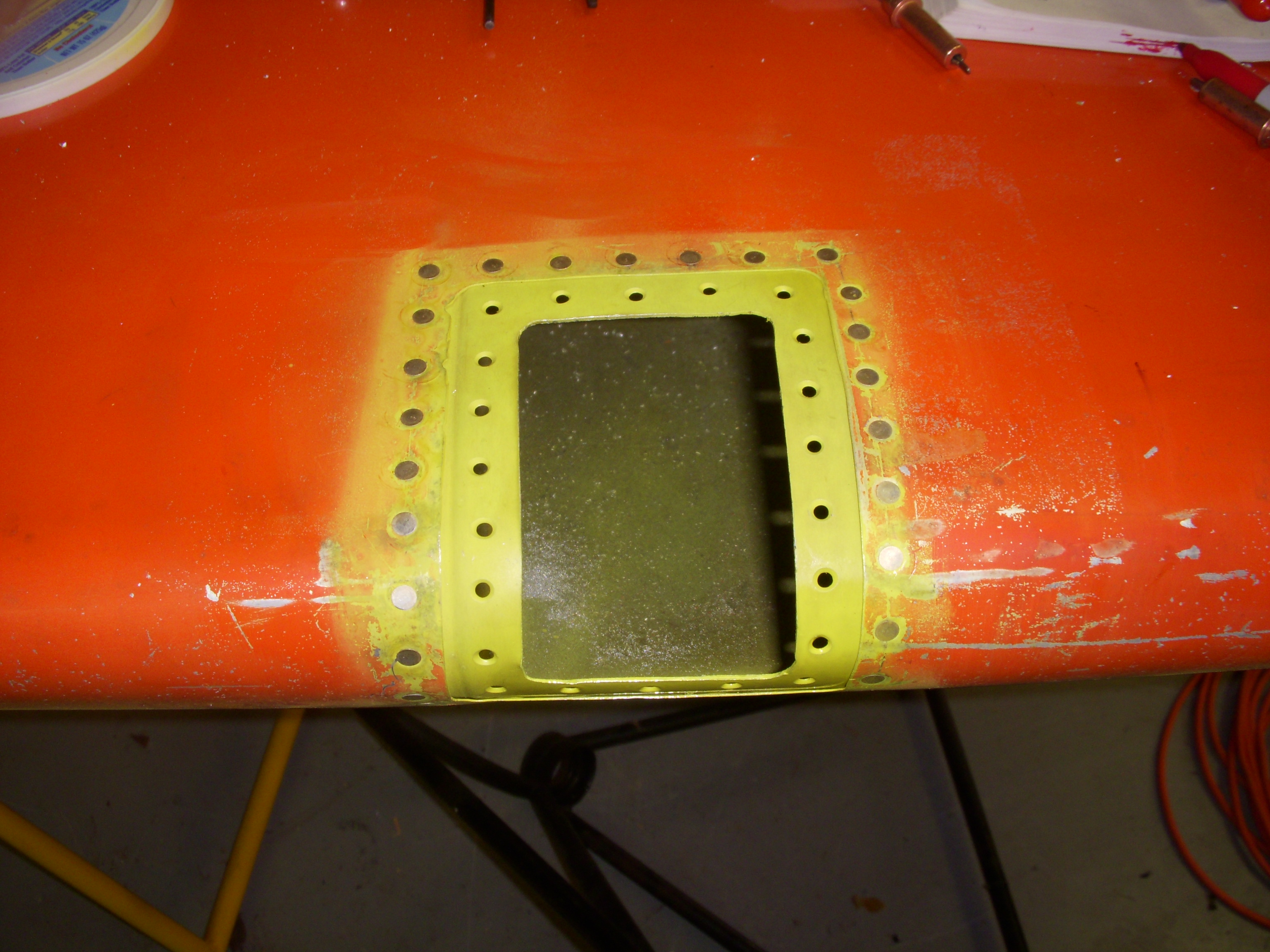
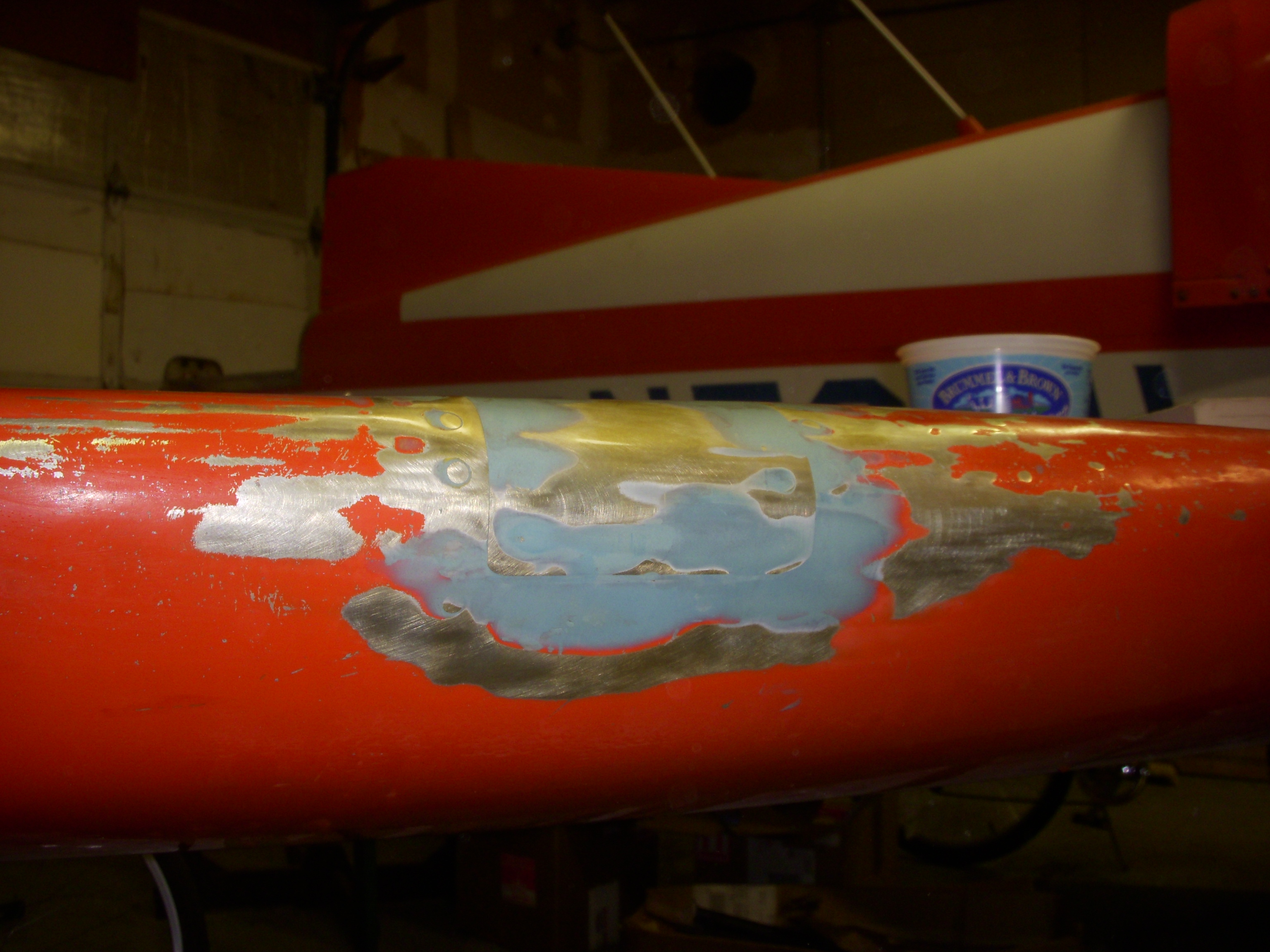
| Filled, faired, etched, Alodined, and ready for primer and paint |
 |
|
Same stage, but from a little "higher" angle angle - note that the wing has
been "upside down" through out this process. The wing repair finished, Darryl and I have hauled it to his shop for fuel tank resealing work. |
 |
This page last updated on 08/06/2018